By Dick Maury
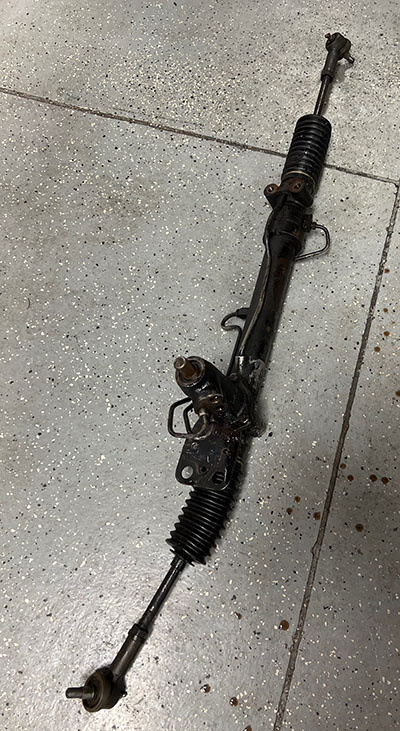
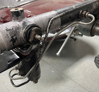
This is to show the proceedure to rebuild the Steering Rack from the Series 3 E-Type. Of course, the first step is to get the rack out of the car undamaged.
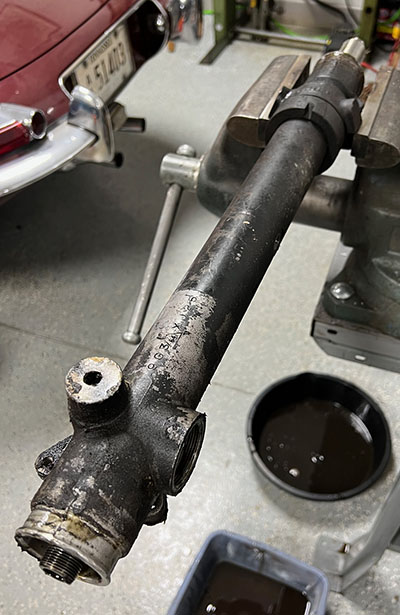
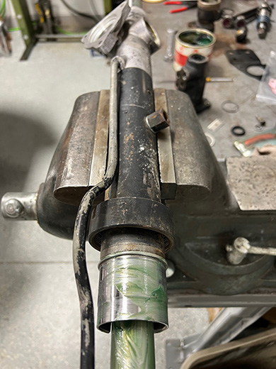
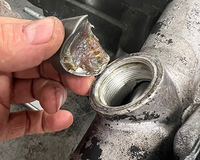
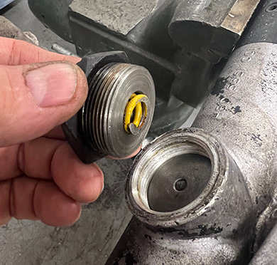
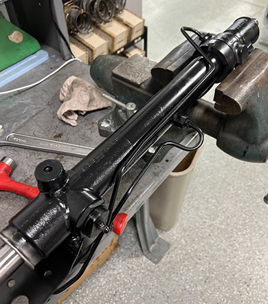
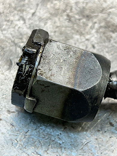
The next step is to put the rack in a vise. I put it in as pictured as I can access all of the lines to get it apart and it is secure. Remove the tie rod ends and rack boots. Carefully bend the inner lock tabs back just enough to be able to turn the tie rod knuckle. Wrench size is 1-5/16". Next, put a bucket under the rack if you have not already. Steer the rack back and forth. This will pump out most of the fluid. Now you can remove both hard lines. Early racks also have a plastic vent line. It can be removed. Later cars use a metal one that will come out later. Next is the adjuster. If you are planning on putting this rack back in the same car, remove the grease fitting and using a punch, turn the rack back and forth until you can align the hole with the hole in the rack shaft. This is the center of the rack. Mark the pinion so that upon reassembly, you can put it back in this position. This will save you having to remove the wheel and center it along with the turn signal cancelor. Now loosen the outside ring nut and then unscrew the whole assembly. There is a yellow spring inside. Use a magnet and remove the tensioner plug that the spring presses on. Now you can unscrew the 3 bolts that hold the head of the rack to the body. Use a soft hammer and tap it until it comes loose with the bracket. Make a note of how the bracket goes.
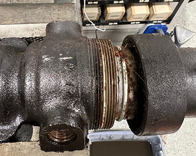
Now shift the rack in the vise so that the screwed end is overhanging for access. Unscrew it. You might have to take a large punch to get it to turn. Notice the threads had some sealant on them. This is not a sealing surface. This was only to keep them from coming loose. Slide the main body of the rack out of the end housinng along with the shaft. Now carefully poke the insert out and do not loose this part as it is not available anywhere. We have to have them custom made as they do get lost. Remove the block that the metal line screwed into. It should have a washer under it. You can now remove the end housing from the vise and remove the flat washer, seal with teflon backup and the o-ring around the inside edge. Slide the shaft out of the main housing. If the seal, washer and serrated spacer do not come out with it, then use a long screwdriver and push them out. Turn the main housing over and remove the lower pinion seal and the washer under it. Remove the upper pinion seal and dust shield by removing the circlip ring. Now the rack should be totally apart. Clean all of the parts and do not discard anything yet.
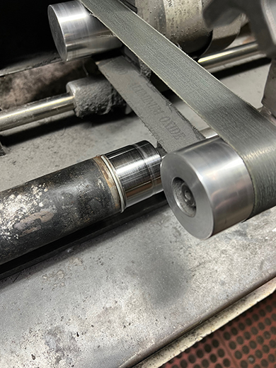
Once clean, the lower pinion housing and the rack surface that it bolts to should be dry sanded to make sure they are flat. They tend to warp over time. Sand paper taped down on a flat surface should work fine. If using a power sanding belt, be careful as it can remove a lot of metal fast.
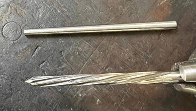
Now that the pinion is out and clean, a common leak problem is the o-ring seal in the top where the internal torsion bar is locked to the splined outer hub. From the factory, it is a straight pin with a interference fit. You will need to punch it out. A special jig is helpful as it keeps the splines from being damaged. Once out, pull the bottom out of the splined area and you will see the o-ring. Note that it is no longer rounded. Replace with a 011 size o-ring, lubricate everything and slide back into place. A taper reamer is needed now to make a new clean fit for a taper pin. Hammer the taper pin in after reaming. Trim both ends and you should have something like in the picture below.
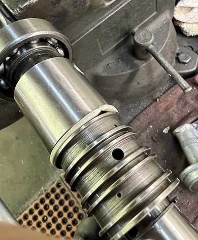
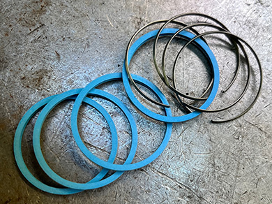
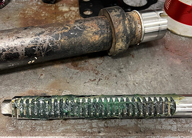
The next step is to replace the nylon rings. These separate the chambers so you have assist left and right. The original plain nylon rings work but in cold weather can shrink and not work until the fluid is warmed up. This is called "morning sickness" which is rather common in steering racks. The fix is to replace with modern seals which have a metal expander behind them. Using a pick, pry them up and then cut and remove.
Using the Factory tool # J32, place the metal expanders on the tube to slide into place on the pinion. Then repeat the process for the nylon rings.
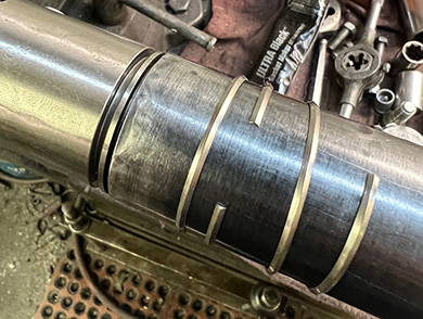
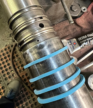
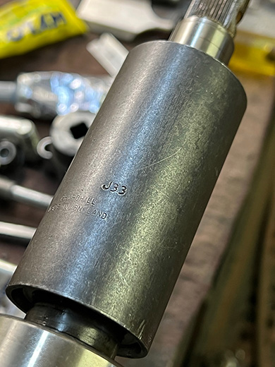
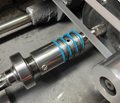
This is what it should look like after install. Now the second part of the tool is the J33 compressor that slides over the rings to compress them back to size. Be very careful to make sure they go back in the slot and not sheared off. You can work them into the slot with your hands initially to help. Leave the tool on them for while you do some of the rest of the rack.
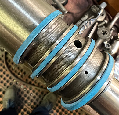
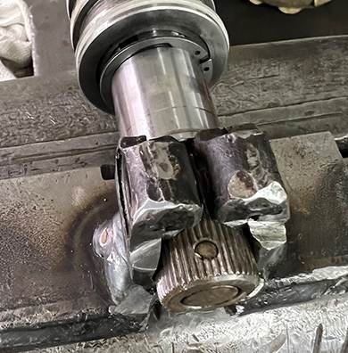
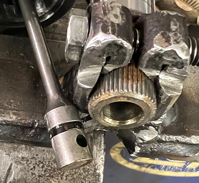
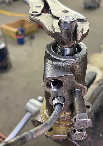
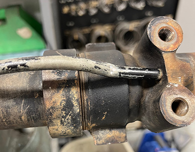
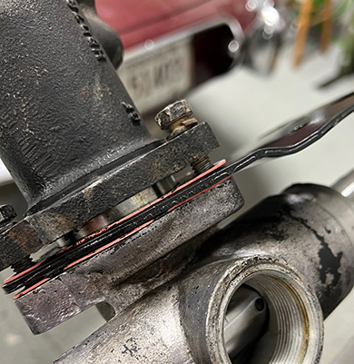
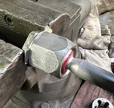
After the pinion has sat for a while (1/2 hour is fine), remove the sleeve and polish the sealing surfaces. After this, I check the bias to make sure the rings are sealing and the rack bias is centered. It it is not centered, there is a adjustment screw on the side. As the head of the rack was apart changing out the o-ring seal, chances are it will need adjusting. In the image below, blank off the two outlet pipes and hook up air to the inlet. With a pressure gauge on the inlet side, you can turn the rack back and forth and the gauge will close off the air in either direction. If not equal, adjust the screw. Although Vice Grips are not the best to use on a splined drive, just don't tighten them down any more than necessary so as to not distort the splines.
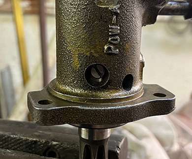
In the image below, you can see the position of the adjustment screw in the housing. This housing was drilled to allow adjustment. If you have a really early rack, there is a pipe plug that can be removed for adjustment. Once adjusted, mark, remove, clean and apply some red loc-tite to keep it from turning. Next picture shows the upper pinion seal, top dust shield and snap ring in place. Once the pinion is ready, lube the seal and the pinion and install in the housing. This part is now done.
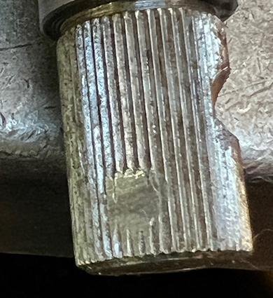
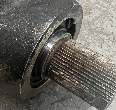
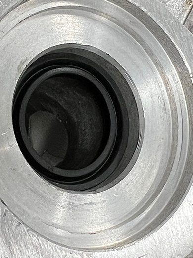
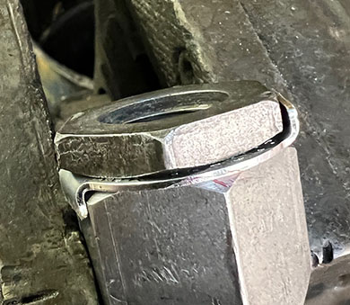
Once the pinion is installed in the head, the polished part should protrude slightly as in the picture below. There are two different heights of pinions and housings. If mixed, it will protrude a lot or not at all.
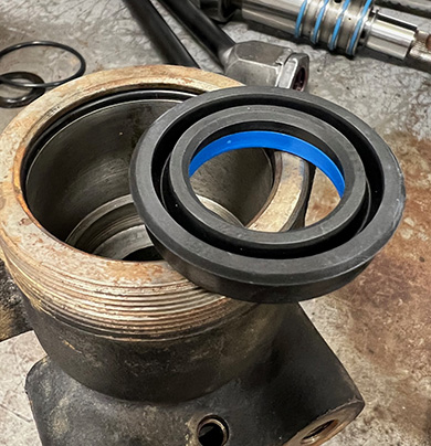
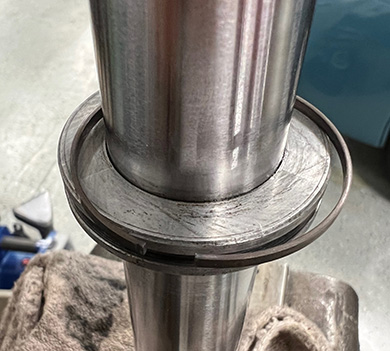
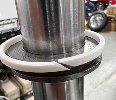
For the end housing, the seal goes in with the orientation shown. There is an o-ring near the edge. Originally, Jaguar used a square cut ring. The o-ring will take up for some light polishing dimensional change. Large flat thin metal washer goes over the seal once installed.
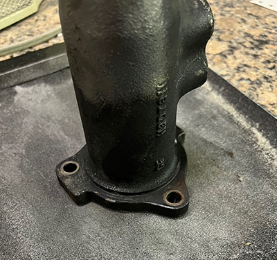
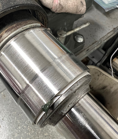
Next step is to polish the housing. This is the surface that goes in the end housing just completed. Rust and pits will leak.
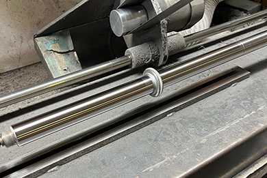
Time to polish the rack shaft. This is good time to check to make sure it is straight also. As you are going to have to slide the seal over the teeth, it is good to buff the edges of the teeth smooth before polishing the shaft. There is also a centering hole on the side oposite the teeth that benefits from a slight bit of grinding. Once polished, place upright in a vice using cloth to keep the teeth of the vice from imprinting on the shaft. You should have a metal expander ring and a white teflon ring. The kits usually have the ring uncut. They need to be cut at a diagonal as shown. At this point, stack the metal pieces and seal as shown. With the shaft lubed, you can take the seal and pull it down the shaft holding the lip away from the edge of the teeth.
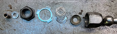
Now coat the shaft and teeth with grease. Synthetic grease recommended as it does not dry out. Smear some grease on the inside of the housing and on the outside of the seal. Carefully insert the shaft, teeth first. Make sure the split ring is compressed enough to go in without chipping. Push all the way in until it stops going in.
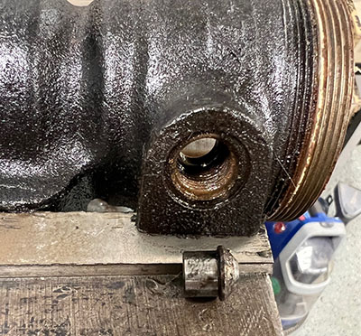
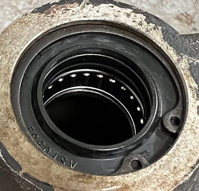
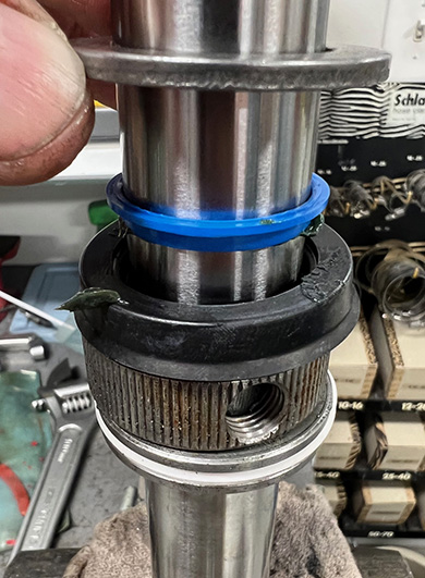
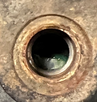
On the side of the rack housing is a hole. This is most likely what you will see in the hole at this point. It has serrations on it so you can turn it with a pic or screwdriver. Turn until you have the holes aligned.
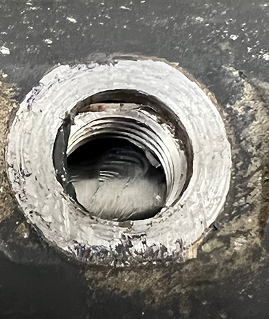
Now screw in the insert with a new sealing washer. Tighten appropriately. Place rack in the vice if not alrealy and install vent tube on housing. Grease up polished end of housing also.
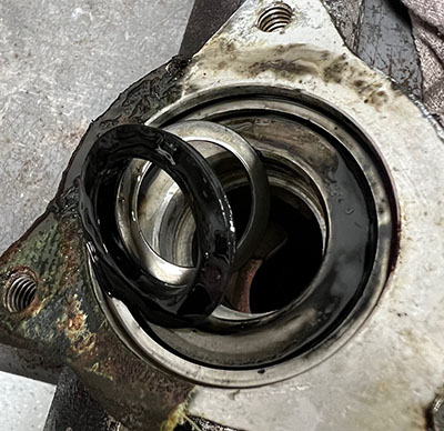
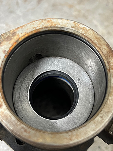
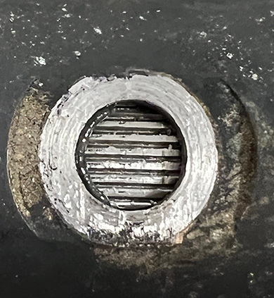
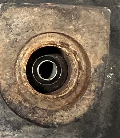
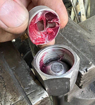
Offer up end housing to rack and main housing. Make sure tube goes into hole and ahand tighten threaded collar. Now look into the hole where the pressure line goes. The picture below right shows that it is not aligned properly. Turn housing to align.
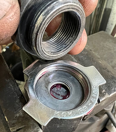
Once aligned, insert metal seal base. This is the base for the high pressure line but also protrudes into the housing far enough to keep the end housing in place. The lower pinion seal can now be installed in the main housing. Don't forget the metal washer that goes behind the seal. It should fit exactly in the recess. The seal has a outside lip that goes in place for a snug fit. If loose or tight, you have a incorrect seal.
Now configure the pinion housing assembly, mounting plate and gaskets as shown. If you sanded off a lot of metal, you will need an extra gasket or oversize gasket(s). Spray gasket sealer is nice to help seal up the paper gaskets. Once the bolts are tight, you can insert the rack adjuster bushing. Be generous with grease. It should go into place without any resistance.
Now install the rack tensioner with spring. Tighten the center until a slight bit of resistance and then back off one third of a turn and lock in place with the outside ring nut. Lines can be installed now. Pay close attention to the orientation as they can be installed backwards and not work properly.
Now plug the outlet port and install a pressure gauge. Check for leakage. Sometimes a small leak just requires a line to be tightened. Window cleaner will show bubbles when sprayed on the leak. Once all is well, a coat of paint will do wonders. Note that for the retailers that buy racks, the rack is also bead blasted and then ultrasonically cleaned so it will appear as new. A lot more work but not needed for a regular home built rack.

Now that the rack is done and working, time to rebuild and install the tie rods. The tie rods on the E-Types and most Jaguars built before 1982 had adjustable knuckles. These are adjusted with shims to get as close to zero clearance as possible. At this point, take the tie rod apart and clean all of the parts if you have not done so already. There are two locking shim plates. One keeps the tie rod from turning on the rack and the other is part of the tie rod that locks the two parts together. If you are careful, only one tab will need to be bent back. There are three so two in one direction and one in the other as in the picture below left. Just bend the one straight enough to turn the tie rod to get it apart. When done and clean, you should have the parts as in the picture below right.
Now is a good time to examine the tie rod and make sure it is straight. Some of the cars get towed and this part gets bent. Worse is if the car had been in an accident. Once you are happy with the integrity of the parts, grease the ball and insert in the large cup and then grease and install the smaller seat as in the picture below left. Now reinstall the shims along with the lock plate and end piece as in the picture on the right. This is a new lock plate but you can reuse the old one if the ears are any good. If the ears are broken off, you can use it as a spacer and tack weld with a mig welder when all adjusted. You just want to keep it from turning. Only one small tack is all that is required and it can easily be ground off in the future.
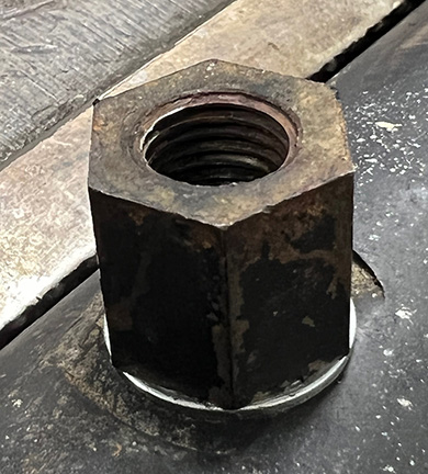
I usually turn the tie rod in the vice to make it easier to tighten it down and check for free play. Size is 1-5/16" by the way. Tighten it down and check to see if there is any free play. Optimally, it should move freely and have just enough resistance to hold the weight of the tie rod horizontally. If loose, unscrew and add some shims. If to tight, take some out. Shims are the same as Jaguar used to centralize the brake calipers. A quick Google search will show them available from the usualls in .003", .005" and .010". Machine shop supply houses also sell them under the name Arbor Shims in even greater variety of sizes.
Notice plenty of grease is used. This is a synthetic grease that I use but regular will work. There is a metal washer that goes in the hole now (Second from left in exploded view). Use the lock tab washer with the "D" shaped inside (JLM-172) and install on the shaft end with the tensioner spring in the shaft end hole. Tighten, bend tab over and install boots. Finished!!
Helpful notes: Sometimes you will come across a tie rod that has been loose for a good while without any grease. The ball will have a ridge on it. You can carefully dress this down using a soft roloc or buffing sander. Assemble without shims or center lock plate and you can check to see if it will operate smoothly. If it is notchy, you can use come valve grinding compound on the ball, tighten and move the rod by hand. Take apart, clean and look for dull spots. This is where the grinding compound had done some work. It is the high spots. A bit more grinding on that area and repeat until it operates smoothly. Then go back to the adjustment and assembly of the tie rod. The XJ6 tie rod is about 1/4" longer so if they are substituted, you will have problems getting the alignment into specs.