BACK
Rebuilding the XKE Manual Rack
by Dick Maury
The XKE used a manual rack from the first 3.8 cars up through the end of the 6 cylinder production in 1971. The Series 2 cars had the option of power steering but that is a different rack which will be covered in another article. If the rack is lubricated as required and the boots are replaced when they deteriorate, these racks are very reliable and require little maintenance. As mentioned, dirt and lack of lubricate is the rack's worst enemies.
The racks on the 3.8s and the 4.2s have different ratios. The pinion on the 3.8 has 8 teeth where the 4.2 has 7. What this does is make the steering a bit lighter but also a bit slower. It is just a matter of personal preference. The rack housings and upper bearing also differ depending on which pinion is used so it is not just a matter of switching pinions. The pictures below show the bearings. The one on the left is for the 3.8, part number B-1516 and the right
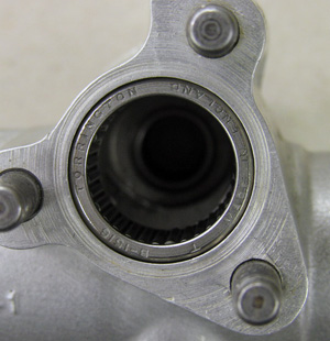
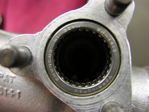 one is a 4.2, part number BH1410. The holes are offset differently to allow for the difference in the pinion sizes. The main shafts are the same as are the tie rods, ends and other pieces. There is also a bearing for the bottom of the pinion which is the same for both racks. As far as building and assembling procedures, both racks are done the same so unless you have multiple racks, there is no problem of mixing parts.
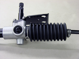
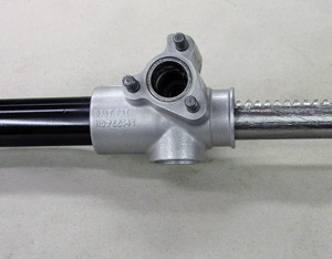
The first step in taking down a rack (besides removal from the car) is to clean off the grease and dirt so that you can see what you are dealing with. Position the rack in a vise clamping on the aluminum housing end. Do not clamp on the round steel tube as this can damage the rack. Check to make sure the rack turns from end to end smoothly. If all checks out so far, the rack should be a good candidate for rebuilding.
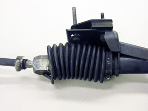
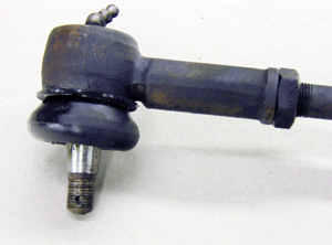
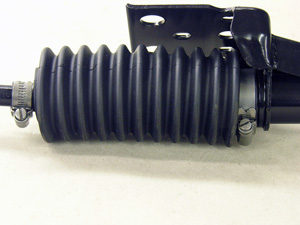
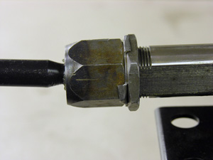
The steering rack used for these pictures was a very original one with the original boots, clamps, tie rod ends and Cheney clamps. Note that on the tie rod end above right that there is a hole in the threaded shaft. This is because the early XKE's used castle type nuts with cotter pins. It also has a grease fitting on the top which is left off of some of the replacement tie rod ends. The XKE tie rod end is also different from the XJ6 tie rod end even though they look similar. The XKE suspension has a far greater travel with shorter tie rods so the end is subjected to more of an angle. Putting a XJ6 end on will cause something to bend or break when the XKE is jacked off of the ground so be careful. A simple way of checking is to fully bend the end of each tie rod and check to make sure the angles are the same.
Also note that on the drivers side, or left side in the USA, that the boot is held on by tied wire. Not real sure why the other three positions were held on by clamps and this one by wire but that is how they did it. The boot on the other side of the rack had torn and if left unchecked, would have let dirt and moisture into the rack. These are readily available so there is no real excuse not to keep them fresh.
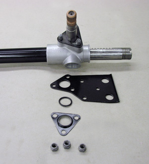
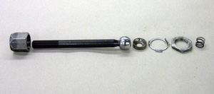
The next step in taking the rack apart is to remove both tie rod ends and then the boots. This will expose the inner tie rod . See picture on left below.

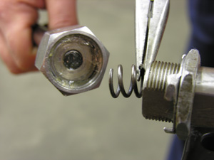
To undo the tie rod retainer, bend back one of the ears on the lock tab. It might require two large wrenches to unlock the two nuts. The outer nut is 1 5/16" and the larger one is 1 1/2". Once unscrewed, you should find a spring. Make sure you save it and all other parts. Now take off the lock washer and remaining nut as in the picture above right.
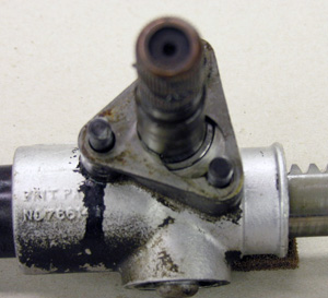
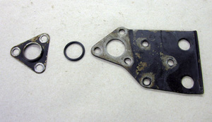
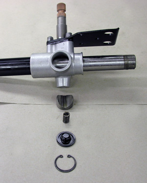
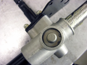
Next, remove the three nylon nuts that hold the plate around the pinion. The top dust shield will now come off with the mounting plate and there should be a o-ring between them.. If the o-ring is pliable, it can be reused. It hardly ever is, so it is best to replace it. Before the pinion can be removed, the pinion tension plate needs to be removed. See the picture on the right above. What is not in the picture are the shim(s). The shims are used as needed and will be covered during reassembly. Save all of the pieces. Now the pinion can be removed along with the retaining plate.
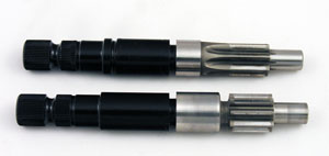
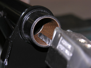
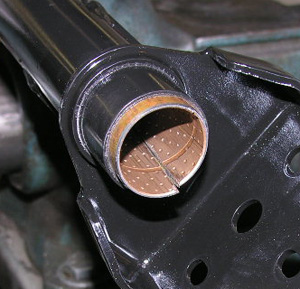
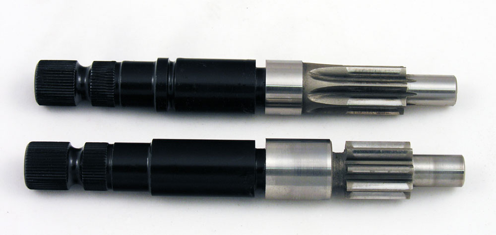
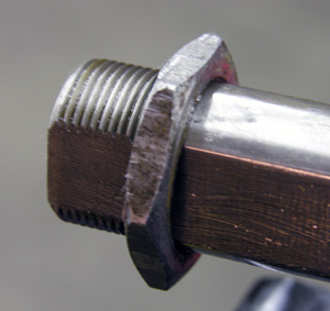
The pinion on the bottom is a 3.8 with 8 teeth. The upper one is the 4.2 with 7 teeth. The upper shaft of the 4.2 pinions has a groove that lets it be identified on the car. In the center picture is the bushing on the right side of the rack (LHD). To get it out, it is easiest to cut it. This can be done with a saw, file or grinder. Once cut, it is a simple matter of sliding it out. To put in the new one, the use of a press is recommended as hammering it in will usually deform it.
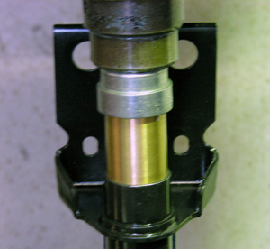
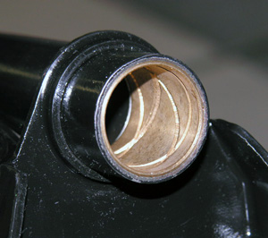
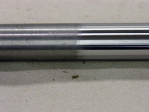
The picture at far left shows the new bushing being pressed into the housing. The next picture shows it installed. The shaft itself should be checked to make sure it is straight. This can easily be done by rolling it on a flat surface to see if it rolls smoothly. I like to polish the shaft. This removes any small pits and makes the rack real smooth sliding in the bushings. If you are going to polish the rack, do so before fitting to the bronze bushing as the shaft diameter might get a bit smaller. I use a center less polisher originally designed for polishing lobes of camshafts. Your local machine shop should have one. Once polished and cleaned, check the shaft where it goes into the bushing to make sure it does not have a taper from wear. If so, now would be the time to correct it. Industrial chrome plating can be used to build up the surface if the shaft is loose in the bushing. Slide the rack into the bushing to check for clearance. It should go in smoothly, with no noticeable side play. If the rack will not go through easily and smoothly, the shaft will leave a mark on the bushing. Use a smooth half round file or a bearing scraper to take off the high spots and then try again. Repeat as necessary until the rack fits into the bushing smoothly with no noticeable side play. Honing or sanding it out is not recommended as it removes metal all around where it might not be needed to be removed. Once fitted, apply a generous amount of grease all over the rack, bushings and the bearings. I use a synthetic grease as it does not dry out or mix with water. This just makes the job last a bit longer but regular bearing grease will work fine.
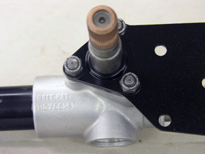
Next, align the shaft where the teeth of the rack are on the side of the pinion. Place the lock plate onto the pinion and insert the pinion into the rack. It might be necessary to turn the pinion to align it so that it will go in smoothly. Now put the mount plate, o-ring, o-ring cover and then the nylon nuts on as in the picture on the right. At this point the rack should steer smoothly. If it does not, take it back apart and determine where the bind is occurring.
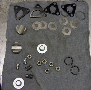
Now apply grease onto the metal bushing and insert in to the hole. The shims at the top of the middle picture are used to adjust the mesh of the teeth. There are extra pieces in the picture as more than one rack was being built at the time. To set the adjustment, put the cap piece (the one that looks like a hat) into the hole without the spring or any shims. Install the e-clip and see if the cap piece has any free play. If so, remove and add shims until it is tight and then remove one shim to give the rack clearance to turn smoothly. Take the cap back off, insert the spring and reinstall the cap piece with the clip as in the picture on the above right.
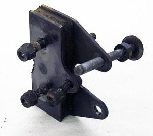
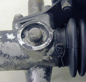
The tie rods are next. I usually polish on the tie rods to remove any plier and rust marks. This should have been done at this point but is not necessary unless you are doing a show car. The picture at the top left shows the tie rod parts in the order that they go onto the shaft. Pack the ball with grease and assemble. Make sure that the spring goes in place as in the center picture. Tighten down the tie rod retainer until the tie rod is firm but not locked. If the tie rod is notchy, then there is excessive wear at the ball and the unit should be replaced. If the rod is just a slight bit notchy, clean off all of the grease and apply valve grinding compound to the ball. Assemble until snug and rotate the tie rod in all directions. Tighten the nut as needed to keep it snug. When it is smooth and snug, take it all apart, clean, grease all components and reassemble. Once adjusted to firm ( where the tie rod will hold up under its own weight), tighten the lock nut into it and bend the ears over to keep them from turning. Now it is time to install the boots. These will slide over the shaft a lot easier if a little silicone spray is applied to the small end of the boot. For show cars, a wire loop holds the boot in place on the rack on the pinion side with the other three positions using Cheney clamps. Any way you choose to do it, just make sure the boots are secure so as to keep the elements out of the rack. Pictures below show the finished product along with the mount and special bolt.